


Table of Contents
Overview − Agile Design and Development for Medical devices
Medical device development and product launches can stir negative feelings. Companies often believe that regulatory requirements put a layer of overhead on the development effort that limits innovation and speed. That does not have to be the case.
These product development processes can be very innovative and dynamic, while still following all the regulatory requirements and best practices for bringing a medical device to market that is safe, effective and improves the lives of patients.
The Agile Method for Medical Device Design is an iterative process that includes all products and product features that are tested, verified and validated, and allows for tweaks, requirement changes, risk updates and compliance updates as needed. Many medical device companies find that with this methodology, their teams have the agility necessary to accelerate development, while meeting all required regulatory standards.
Greenlight Guru’s Design Control, Risk Management, and Quality Management software platform is flexible in nature to support an Agile method, along with other popular methodologies. The purpose-built solution with 21 CFR Part 820, ISO 13485 and IEC 62366 standard best practices built into every feature of the software, removing the regulatory burden from companies. With full visibility and complete traceability, teams can maximize and accelerate all design and development efforts.
ISO 13485:2016 section 7.3 and FDA 21 CFR 820.30 outline the Design Controls required in order for a medical device manufacturer to design and develop a medical device that is brought to market. These regulatory standards require the device maker to conduct:
- Design and Development Planning, i.e., identify the scope of the project and how all aspects of ISO 1345:2016 and 21 CFR Part 820.30 will be met.
- User Needs, i.e., identify the Use Cases and the product requirements from the end user(s) point of view.
- Design Inputs, Product Requirements, Marketing Requirements, and Regulatory Requirements (regional or international applicable standards) for compliance.
- Design Outputs, the actual engineering and design of the medical device.
- Design Verification and Validation, i.e., medical device testing to ensure the output of the design meets the User Needs and the Product Specifications as laid out.
- Design Transfer to Manufacturing.
Design Controls have been put in place to protect the end user, but they do not end with the transfer of a design to manufacturing. Design Controls apply to all changes to the device itself during the manufacturing process of the device, as well. The changes are part of a continuous, ongoing effort to design and develop a device that meets the needs of the user and/or patient, and may include performance enhancements, or corrective actions resulting from field failures.
Any time a new medical device is in development, the design control process is revisited many times throughout the lifecycle of the device. This is a fact of medical product development, and this guide will showcase the many opportunities this approach provides for continuous innovation and creative problem solving amongst teams.
The Waterfall Development Process
Historically, the most popular method used for medical device product development has been the Waterfall Development Process, which takes a simplistic approach. In a Waterfall (WF) model, by isolating planning from design from importation from launch, each phase must be completed before the next phase can begin. There is no overlap in the phases. In this approach, the whole process of medical device development requires linear and logical separation of phases. The outcome of one phase acts as an input for the next phase, in sequential order.
Some companies use a Stage-Gate or Linear Sequential process - these refer to the same waterfall-type process. WF models have a sequential design process in which progress is seen as flowing steadily downwards (like a waterfall) through the phases of Conception, Initiation, Analysis, Design, Construction, Testing, Production/Implementation and Maintenance. Translated into MedDev terms: Feasibility, Design & Development, Verification & Validation, and Design Transfer.
With WF processes, years may elapse between the period of defining requirements and actual implementation, thus compromising any rapid response to requirements. Standard practice change management controls, such as an engineering change order (ECO) approach, intend to allow requirement changes, but fail to handle change efficiently and effectively.
An example of the risk in making changes to requirements using a WF approaches can result from capturing the change and the ripple effects to all other elements or domains (User Needs, Marketing Requirements, Compliance, Verification and Validation, etc.) While change may be controlled, such an approach can unnecessarily force design and development to cycle back through the entire sequence. This disruption can lead to increased costs and schedule challenges, resulting in higher cost products, or ones with reduced features.
In 1997, FDA published “Design Control Guidance For Medical Device Manufacturers,” illustrating the Waterfall design process, which is shown here:

The development process depicted in the example is a traditional waterfall model. The design proceeds in a logical sequence of phases or stages. Basically, requirements are developed, and a device is designed to meet those requirements. The design is then evaluated, transferred to production, and the device is manufactured.
Medical device manufacturers historically have assumed the Waterfall process to be the best way of managing design artifacts, reviews, and approvals. The Waterfall approach packages documents and reviews them in neat bundles, but in doing so, places emphasis on organizational quality system process compliance, rather than the construction of a quality product that addresses user needs.
There was historical use and bias towards Waterfall, but even regulatory bodies have documented a pivot. Contrary to popular belief, FDA and other regulatory bodies are not partial to Waterfall methodology. In fact, the FDA remains neutral in this regard and states in The Design Control Guidance the following:
Although aspects of their utility are sometimes described, they are included in the guidance for illustrative purposes only. Including them does not mean that they are preferred. There may be alternative ways that are better suited to a particular manufacturer and design activity. The literature contains an abundance of information on tools and techniques. Such topics as project management, design review, process capability, and many others referred to in this guidance are available in textbooks, periodicals, and journals. As a manufacturer applies design controls to a particular task, the appropriate tools and techniques used by competent personnel should be applied to meet the needs of the unique product or process for that manufacturer.
We believe that this shift in preference towards a broader view for all new medical device development is a positive signal from our industry that a shift is occurring. We believe that this shift encourages a new way to think and approach the medical device design and development process. This shift is at its heart Agile.
Adapted Agile Manifesto
The 12 Tenants for the Medical Device Design Control Manifesto are adapted as follows:
- The highest priority is to satisfy our customer through early and continuous delivery of work product.
- Welcome changing requirements, even late in development. Agile processes harness change for the customer’s competitive advantage.
- Deliver working prototypes frequently, from a couple of weeks to a couple of months, with a preference to shorter timescales.
- Business people and developers must work together daily throughout the project.
- Build projects around motivated individuals. Give them the environment and support they need, and trust them to get the job done.
- The most efficient and effective method of conveying information to and within a development team is face-to-face conversation.
- Working prototypes are the primary measure of progress.
- Agile processes promote sustainable development. The sponsors, designers, developers, and users should be able to maintain a constant pace indefinitely.
- Continuous attention to technical excellence and good design enhances agility.
- Simplicity–the art of maximizing the amount of work not done–is essential.
- The best architectures, requirements, and designs emerge from self-organizing teams.
- At regular intervals, the team reflects on how to become more effective, then tunes and adjusts its behavior accordingly.
Context for Medical Device Design
With an Agile Medical Device Development process, individual Features are identified that meet User Needs. With each Feature, each design element is considered; the Design Inputs (Requirements), Standards Compliance, Regulatory Strategy, Risk Elements, Verification Test Cases, Design Element or Design Output, Verification Test Case and Trace (Risks, Verification, Validation, Requirements, Test Cases).
A design review is held at the completion of a Feature or Set of Features to ensure that, per ISO 13485 7.3.5, the results of design and development are evaluated as to whether they meet requirements, as well as to identify and propose necessary changes.
Design reviews are essential in all regulatory documentation, but do not need to be considered “gates” through which every product goes through as a whole. We propose the design review can be applied to elements of the design throughout the development process and in each system layer or domain.

Agile Medical Device Development Process Model
These Features can be bundled in a new and intuitive way to leverage the tools in the greater Agile toolbox. When all these bundles are completed and all the Features are executed, the design and development of the medical device is completed. The summation of all of the Features is the medical device.
It should be clarified that though each Feature has test cases identified for Verification and Validation (V&V) tests, the medical device would need to go through a formal V&V phase as with the WF process. By utilizing the Agile medical device design process, however, all Test Cases have been authored, traced to requirements, risk or compliance elements, and preliminary tests on the whole device have been performed.
What remains in the V&V phase has significantly lower risk and potentially shorter time duration. This final phase is a formal execution of all tests on the full system, an aggregate of the Features, the completed medical device.
Advantages of Agile Development
There are several unique characteristics to implementing an Agile development process, making it attractive to medical device development, which include: continuous quality, visible progress, improved risk management, and a safe and effective product. Let's expand upon each of these benefits and what they mean to product development teams.
Continuous Quality.
Working Features are produced frequently throughout the development cycle. Verification is part of Agile development and is realized through unit tests, frequent builds, iterative manual verification, and regression testing. System integration time is also reduced due to frequent, smaller integration efforts.
Once Continuous Quality has begun within a team, department or company, the defects are found often and soon, significantly reducing project and product risk. This is a powerful shift, and is a byproduct of adopting the Agile development process.
Progress Visibility.
All stakeholders—marketing, product management, executive sponsors, quality, regulatory, manufacturing, customers, etc., see tangible progress as Features are demonstrated during each sprint, promoting early review and feedback.
Progress Visibility also has a cultural component, as well. As the product makes incremental progress towards the finished product deliverable, there is a sense of both personal and team accomplishment. Through well-known Agile practices, such as stand-ups and regular sprint reviews (we will expand on these practices later in the piece), each team member is given the floor, alongside the whole team, to share what is finished, what will be accomplished next and what impediments might be in the way of completion.
As the team makes progress towards the goal, visual indicators are a reminder that the time and effort spent by each individual in their contribution to the product has a dynamic and living quality. A quality culture that promotes incremental progress is a positive shift for teams that are accustomed to years-long design phases from the Waterfall product development style.
Improved Risk Management.
The iterative nature of Agile development provides for a consistent identification and update of risks.
In Agile, the greatest uncertainty and most crucial aspects to the performance of the new product are worked on first, tackling the problem head-on. This approach is incredibly powerful in several ways. By attacking critical and ambiguous items first, the team can discover if the product could be developed in a more simple and straightforward way or determine if the product is worth developing at all.
There is a preference towards simplicity with Agile. There is clarity and focus when a team determines what the product will not do and will not include. This simplicity can pay dividends later when overall product cost is compared to the initial estimate, or the initial V&V phase determines how to match claims to performance.
Something commonly referred to in Agile development is the idea to “fail fast.” For example, if it is found that a critical subsystem will not work with a current set of components, the company can make a fact-driven decision to not proceed to the next stage of manufacturing. In this case, the company failed fast by identifying critical roadblocks early-on and can now decide whether to shelve the product temporarily, or invest in new resources to resolve the issue.
Product Success.
The purpose of our research and efforts as medical device professionals is to accelerate and improve positive patient outcomes. In order for that to be accomplished, our products must meet customer needs.
Agile reinforces and encourages frequent and ongoing customer contact at all times. When there is a close and ongoing relationship with customers, requirements may change. This brings us directly to our definition of product success. The increased visibility and willingness to accept those changes during the development process guarantees the construction of a successful product that meets user needs.
Any changes that take place during the course of the product's development are rolled into the active development process, rather than a re-trek of the entire process that would take you back to square one.
Developing a Medical Device as a System in Light of Agile Methodologies
Using a Systems Engineering (SE) approach can be effective when working with today’s complex medical devices, as it addresses the entire device system and determines the following features:
- All subsystems (a discrete selection of components that work together to perform a function) that make up the full system.
- Each subsystem-to-subsystem dependency.
- All of the rules that will need to be drawn up in order for the subsystems to work together, or integrate.
- The order in which those rules will be drawn up so that subsystem integration occurs correctly.
This approach differs from the traditional linear product development approach by dividing the whole product idea into subsystems and—beyond simply establishing requirements for those subsystems—devising an order in which each subsystem must be defined. It also determines which dependencies between subsystems are needed for proper operation.
Both subsystem-specific engineers and the overall systems engineer roles are necessary to establish the requirements for the interactions and integration of the subsystems—that is, what makes the whole system work together.
To kick off the SE process for a complex, portable medical device, the user and stakeholder needs must first be defined and communicated to the product development (PD) team. Once the PD team has a firm grasp of what the client wants, the team will typically brainstorm ways in which those wishes can be fulfilled.
At this point in the discussion, there might be vocal concern that “my project is simply too complex to make Agile work.” We have found these fears are not founded in fact. We have seen that the more complex a system is, the more Agile PD techniques will benefit project efforts. As mentioned previously, let’s first look at the system through the lens of risk.
A complex system must perform two things effectively:
- Perform tasks within subsystems correctly and safely.
- Perform tasks across the full system correctly and safely.
Looking at these two dimensions of the system functionality, every task that a product must perform can be found to have two sets of acceptance criteria. In Agile, this acceptance criteria is often referred to as “Done Statements” for each task.
Your organization might have a different, but convincing concern, “our project is a simple and/or derivative of an existing product and a new process adds uncertainty.” Simple or derivative products are actually excellent places to try this new way of thinking in a small and segregated team, in order to gain factual evidence for the benefits of an Agile medical device development approach.
In either case, there are tasks only the system as a whole can perform, and therefore acceptance criteria can only be found once the entire system is assembled and connected. However, if tasks are being performed by a subsystem, this helps to subdivide all functionality into its smallest component, to push testing and risk to these lower subsystems.
Once the subsystems can interface as a set of independent functional products, each one can be taken from highest risk to lowest risk. Let’s take a theoretical system and see it through the eyes of Agile risk mitigation:
- Power Management: borrowing from legacy product
- Mechanical Design: borrowing from a legacy product
- Manufacturing Techniques: matching a similar competitors' product
- Software User Interface: not used by this company or any other company before
- Disposable Components Must Be Eco-Friendly: not used by this company or any other company before
Using this simplified example, we can see the team will need to focus early on Software UI and Disposable Components since they do not leverage legacy subsystems, team knowledge or experience needed to make sure these new components work correctly within the overall system.
Systems Engineering for Complex Portable Medical Device Development
As stated earlier, agile works in simple and complex products alike, but for the benefit of our discussion, we will use a real-world complex example for this next discussion.
Next up after brainstorming are the following crucial steps:
- Defining subsystems that will work together to make up the whole device system.
- Creating a subsystem architecture and depicting it as a flow chart that shows the links between the subsystems.
- Prioritizing the subsystems, which is the keystone of the SE approach: For which subsystem will requirements be defined: First? Second? Third? This ordering of study and activity enables efficient movement through the PD process. “Locking down” the priority-one subsystem will lead to the definition of requirements for the priority-two subsystem, and so on. Concepts can be generated for each subsystem and then tested against each other or with subsystems that have been thoroughly characterized and defined.
- Developing subsystem-level requirements for the device concepts (performed by the engineering teams) and concurrently developing system-level requirements (done by the systems engineer) with an eye to subsystem integration.
- Integrating the “locked down” or successful subsystems: Once subsystems A and B, for instance, are complete and functional, development of a prototype of an integrated subsystem AB can be initiated. As integration occurs, product development moves from meeting requirements to creating actual specifications.
As one example of how a medical device system can be seen as a collection of several functional subsystems, let’s look at the example of an insulin infusion device. Several subsystems are present in the entire device, including:
- canister design and drug formulation,
- user interface,
- drive-mechanism cocking,
- drive mechanism (spring),
- stem and opening,
- canister activation,
- dose-counter mechanism, and
- an inhalation-activated trigger.
Rather than jumping right into the creation of a total-product concept that incorporates all subsystems at once—thereby making it difficult to define what is critical about each subsystem and its components—the systems engineering (SE) approach first establishes the individual subsystems, determines the links between them, prioritizes those links, defines and tests in a logical order, and then finally, integrates the subsystems.
As you can see, SE and Agile product development methodologies work together here in the details of the planning effort. As we did for the simplified system, we will go one or two steps further now with each subsystem. In addition to looking at each subsystem only from the point of view of risk based on familiarity, we add the critical attributes of subsystems that function together in intermediate subsystems and the ways in which each subsystem can be tested alone, verses with one or more sibling subsystems.
We have an example from our portfolio that we can use to shine more light on the subject. In a hearing instrument, the software an audiologist uses to test and then prescribe the right output algorithm is called the Fitting Software. The Fitting Software is similar to most software in many medical devices in that it has two sets of requirements.
Fitting software needs to be clear and intuitive for the audiologist to find the features they need at the time they are prescribing the right set of programs for the patient, but then also, these settings from the user (audiologist) must also make changes to the functionality of the hearing instrument itself (the overall system).
In defining the requirements of the fitting software subsystem, we define a workflow from hearing test, through initial fitting recommendation, to final on-ear test with the patient in wireframes, and add all the required colors and fonts needed for consistent branding for the product line.
Using Agile de-risking, we start with the newest and/or riskiest new features or workflow task patterns to be mocked up first for customer feedback. Testing of software screens can be performed with beta group of audiologists in order to ensure the workflows, button, font, and screens all make sense in order to perform the new tasks without confusing the typical tasks of a patient fitting.
In parallel, the overall architecture of the system helps to define all the firmware and embedded control interfaces that will be used by the fitting software to turn the product on/off, volume up/down, button controls to switch through various algorithms selected by the audiologist.
As with the user interface, the fitting software team works with all the embedded control and firmware teams, from the highest risk items to the lowest, in order.
Once the entire system is assembled, all of these subsystems connect and audiologists bring in real hearing loss patients in order to fit them with brand new hearing instruments, with these new features tested first. All interfaces are tested in the context of the completed hardware plus software system. Even tests performed at the subsystem level are performed again when the entire system is connected, in order to insure full integration and that there are no broken interfaces.
Agile Development Use Case
Long gone are the days when requirements are locked in stone for a product without the ability and agility for a product development team to make adjustments through the course of a project. Let’s look at another real-world example.
We had the opportunity to assist a client with the development of a change to their existing breast pump. Well into development and past the classic “planning” phase, the customer discovered that the market needs and preferences were shifting away from typical disposable batteries and towards rechargeable batteries.
This was not a trivial shift, but with the Agile development method we broke down the effort into a manageable effort. This started with creating the Agile Card for the feature update.
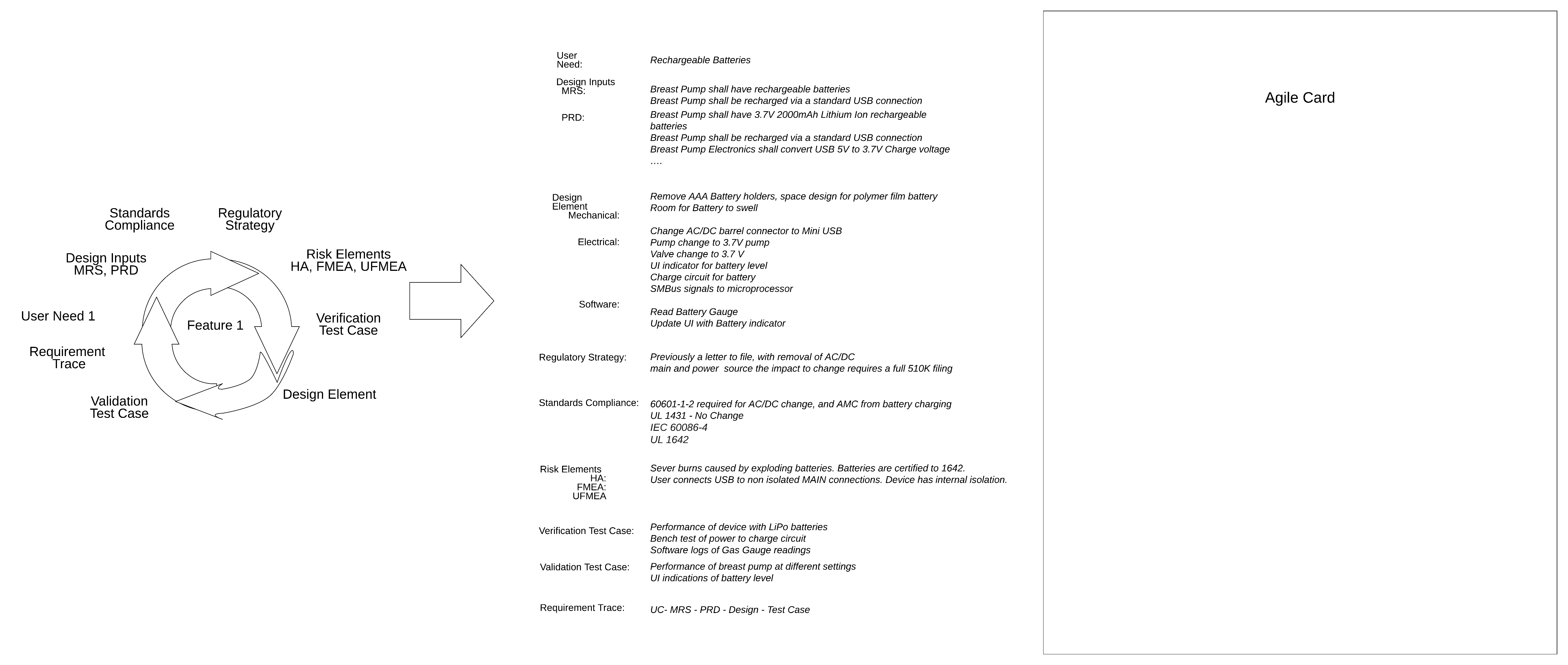
- Design Inputs
- Market Requirements Document (MRD):
- The MRD is typically the story of the product, its primary use cases and the environment where the device will be used
- Breast Pump shall have rechargeable batteries
- Breast Pump shall be recharged via a standard USB connection
- Product Requirements Document (PRD):
- The PRD is more of a technical understanding of what will be needed in order to achieve the use cases found in the MRD.
- Breast Pump shall have 3.7V 2000mAh Lithium Ion rechargeable batteries
- Breast Pump shall be recharged via a standard USB connection
- Breast Pump Electronics shall convert USB 5V to 3.7V Charge voltage
- …
- Market Requirements Document (MRD):
- Design Elements
- Mechanical impact: The AC/DC power wall wart is removed, replaced with a USB cube. The AAA battery compartment is removed, replaced with a non accessible LiPo battery compartment. Room should be made for battery to expand while charging to remove risk of fire.
- Electrical impact: Removal of 9V wall wart, replaced with USB charging - 5V. Internal pump and valve need to be specified with new voltage or voltage needs to be boosted. Charging for battery needs to come from 2A USB connection. Battery SMBus signals need to be routed to microprocessor. User interface needs update to reflect battery level.
- Software impact: The Software needs to read from battery gas gauge, monitoring temperature of battery while charging and use. Charge remaining needs to be updated to User interface.
- Regulatory Strategy
- The current strategy for the design change was a letter to file since it did not impact intended use and engineering changes that would necessitate a 510(k) per FDA, on Deciding When to Submit a 510(k) for a Change to an Existing Device.
- The change of main and secondary power sources is an “energy change” per Deciding When to Submit a 510(k) for a Change to an Existing Device and thus requires a 510(k) premarket notification filing.

At the next planning meeting, the team reviewed the new feature set and planned the development. The Agile approach to attacking highest-level risks first helped to mitigate downstream risk and cost. The change did have an impact on the overall timeline and schedule for the entire product delivery timeline. It was mitigated by avoiding the additional overhead of change management documentation found in classic and waterfall medical device product development projects.
Features Broken Down into Agile Cards

Sprint Planning with your Agile Cards
With the goal being to convert these features cards into Agile sprints, it must be determined by the “product owner” who serves as the voice of the customer, which elements of the feature are most urgent to least urgent.
Creating your User Story Narrative
In order to get the entire product completed with top speed, the cards will be prioritized into 2-week sprints. We must use the Agile concept of a story and go into some detail on the benefits. The definition of a story and story card comes to us from Wikipedia:
User stories are often written from the perspective of an end user or user of a system. They are often recorded on index cards, on Post-it notes, or in project management software. ... A requirement is a formal description of need; a user story is an informal description of a feature.
This definition is intriguing and useful for our application in the medical device space. First, medical devices must already be organized and documented in the form of user needs, based on all regulatory protocols. We can further note that user needs, intended use, and use cases can all be used to convey the same goal. The purpose (or use) of the product is covered with user stories.
Second, we take each of these statements of use or purpose and separate them physically from each other using a tangible or virtual card. This decouples this story from all the others, although for our use in SE within medical devices, we can have “families” of cards with the same subsystem function or purpose to use the same color. In Agile product development software terms, they can all come from the same “epic” or higher overarching theme.
Third, we can use informal language in order to speak more closely in terms that the recipient of this card can execute. In previous generations, we needed both a market requirements document (in the language of the use and environment where the finished product will be used) and product requirements (details sufficient to perform the technical tasks to perform the use). Stories can stay in simple conversational terms that are clear enough for a technical resource to understand when the task has been successfully completed.
Finally, missing from the definition is a critical aspect of a story card: how the task is to be performed will be at the discretion of the development team and the developer receiving the card. The terms “development team” and “developer” came from software engineering which is the original environment where the terms were conceived, but can still be applied to the medical device product development team for our use.
Developing your Sprint Plan
Let’s spend a little time now with the definition of the sprint planning and sprint itself. Once all of the user stories for every subsystem are documented in the story card communication style, the “Product Owner” will then give each a score of priority and/or urgency. The Product Owner is the voice of the customer for the overall product to be built.
Separately, the “Scrum Master” will identify the amount of work the development team is capable of delivering in a set period of time. The Scrum Master’s role on an Agile product development team is to keep everyone fluidly working, and to clear any bottlenecks that might arise.
Once the team’s total capacity in a given time period (known as the sprint) has been established and once all stories have been prioritized from most urgent to least urgent, the team will grab the number of stories equal to the capacity. If the result of each time increment will deliver a complete feature or set of features, the team knows that the first balance of sprint duration has been discovered.
This process of creating, sorting, and collecting stories into sprints will be messy and imprecise for your first few sprints if you are new at this process, but hang in there. The process will improve as team members begin to understand each other, their skills, the team capacity, and the quality of the stories as they are written.
All of the cards can be organized within the sprint into these simple categories:
- To-Do: tasks needed for this sprint that have not been started
- Doing: tasks needed for this sprint that have started but are not yet completed
- Done: tasks that have been completed and tested against the card definition.
Finally, to make all of this work smoothly, Agile product development process recommends a practice of daily development stand-up meetings. There are 3 goals for this session for all members of the development team:
- Each developer reports (i) the task(s) they have assigned to them, (ii) what they will do today to complete these assignments, (iii) what they completed yesterday, and (iv) the barriers they perceive to their completion.
- The Scrum Master can monitor the overall progress of the development team and provide assistance to clear any barriers identified.
- The Product Owner can monitor all tasks as they are due to receive for acceptance testing.
Let’s now circle back to our breast pump example. For the purpose of this example, within this 2-week sprint, there are 3 engineers working on the project allowing the team to complete 6 weeks of effort every sprint. Since we only have 6 weeks of capacity from our team and 12 total weeks of effort, we will need to prioritize certain tasks over others to complete the entire set of work.
If we look at the entire list of feature cards from our previous section, we will prioritize the cards accordingly:
Sprint 1
- 6 weeks of capacity
- Task 1 (2 weeks) + Task 5 (3 weeks) + Task 2 (1 week)
Sprint 2
- 6 weeks of capacity
- Task 3 (1 week) + Task 4 (3 weeks) + Testing of the Entire Feature (2 weeks)
As you can see, we are completing the entire feature in 2 sprints, and we have selected certain tasks to be more urgent than others.
Advanced Concepts of Agile Methodology
In this section, we will be introducing advanced concepts related to the use of the Agile methodology in the development of medical devices.
In the previous section, we mentioned that the process to create, sort and organize stories into sprints can be messy at the start, but it gets better over time.
As we introduced these concepts, there were some assumptions that were built into the definition of certain terms:
- User Stories
- Assumption is that they are clear and self sufficient for a “developer” to receive, estimate and perform the work found in the story.
- Team Capacity
- Assumption is that the scrum master understands the skill and capability of the development team in the context of story complexity. E.g., This team can perform 30 simple stories, 15 simple and 5 complex, 10 complex within one 2-week sprint.
- Sprint Duration
- Assumption is that the duration selected is long enough for useful features to be finished in each and every sprint. E.g., Within 2 weeks, this team can produce the capacity from bullet #2 without external assistance.
In an organization where Agile practices are still very new, there will be growing pains associated with all three of these areas. There are tools that can help to identify if one or more of these three assumptions (or variables) is grounded in reality.
Burndown Chart

The first tool is a Burndown chart, depicted in the image above.
Within a sprint, the burndown is a visual representation of the effort being completed from start to finish as the sprint progresses. Let’s use the analogy of your smartphone navigation app. A burndown chart will show you in real time how close you are to your destination relative to the total length of the trip at the time you began.
If you are traveling from Chicago, Illinois, to Indianapolis, Indiana, the navigation app will tell you that this is typically a 2 hour 56 minute drive and take 184 miles. After 2 hours, if you have only traveled 80 miles, what have you learned? Yes, you may have gotten caught in an unexpected traffic delay, but you have learned even more. Relative to your starting assumption, you are behind schedule. That is exactly what a burndown chart does.
At the start of a sprint, if you know you have the capacity to deliver 30 simple stories per 2 week sprint, and 30 have been assigned and accepted by the development team, your assumption at the beginning is that all 30 will be done after 10 working days. If, after 5 working days the team has not delivered on 15 out of these 30 simple stories, the scrum master knows that there has been an issue within the first few days at the daily stand-up meeting, if the developers have all been honest about their task assignments.
The burndown chart can be useful in large or geographically diverse agile product development teams where daily stand-ups are not identifying a sluggish or slow sprint. We will get back to this idea after we introduce the next advanced tool.
In the example of our medical grade breast pump, let’s investigate Sprint 1. Within sprint 1, at the beginning, 6 weeks of effort are all To Be Done and none of the effort is done. This indicates 6 weeks on the y axis. After 5 days of this sprint, 3 weeks of effort have been put into the project. Logic would dictate that as the x axis value of time is now at 5 days, the y axis value of effort should now be 3 weeks.
If the team has not yet completed any tasks, the y axis will still show 6 weeks of effort and the Scrum Master (project manager) for this project will alert the team that tasks are behind schedule and determine if mitigation plans are needed to accelerate. On the contrary, if after 5 days all 6 weeks of effort is classified as completed or done, the Scrum Master and the Product Owner can reach into the second sprint tasks and start at the most urgent tasks early.
Velocity
The second advanced concept in Agile development we can apply to medical devices is the concept of Velocity. Similar to Burndown, Velocity uses the variables of effort over time, but we can use this rate of progression as an early predictor of overall project completion.
Coming back to our driving analogy, if we are driving from Chicago to Indianapolis and we are behind in our original schedule, we could speed up (within the speed limit of course). With a medical device Agile product development project, if the burndown chart indicates the sprint is moving slowly, identifying this very early and responding can increase overall team performance towards the original goal.
Given that development Velocity is directly proportional to team capacity and story simplicity, teams can do three things to improve Velocity:
- Improve skills, through training, of the existing development team in order to accomplish more per developer.
- Increase the size of the existing development team.
- Break complex stories into several simpler stories.
Beyond the variables that go into increased Velocity, there are more ways in which a proactive Agile product development team can respond to slow or sluggish sprints:
| Cause | Response |
| Stories themselves are poorly constructed | Step back and have the Product Owner scrub all stories |
| Complexity of the stories may have been underestimated | Scrum master can ask the product owner to remove a few stories from the existing sprint |
| Skill of the developer not well-matched to the needs of the story |
Scrum master re-assign the task to a different developer |
| Overall team capacity was underestimated | Development team can grow in size with internal or external candidates |
Device Completion Prediction
Let’s assume that the size of the team is the same as the one outlined above, where we are actually delivering 6 weeks of effort every 2 week sprint. Furthermore, if we assume that there will be a grand total of 100 weeks of effort to complete the entire development project (12 weeks for this feature, but 88 more weeks for all other features total), Velocity tells us that the entire project will be completed in 17 sprints (or 34 weeks).
Final Thoughts
Through the Agile Design and Development methodology, all elements of medical device design are being exercised - user needs, design inputs and outputs, verification and validation, and reviews; in addition to complete traceability and risk mitigation from start to finish. If done well and meticulously, the ultimate outcome is a quality medical device that meets users needs, regulatory requirements and is ready to advance to its next lifecycle stage.
Utilizing an Agile development process can improve risk management and quality management by means of frequent testing, deployment, and integration; better and earlier visibility of demonstrable progress; and most importantly, ensuring that medical device companies are releasing the right product that fulfills current user and business needs.
For medical device companies interested in utilizing an Agile-based methodology for product design and development, it’s important to make sure it is executed using the right quality management system. We at Agile Medical Device Design use Greenlight Guru’s medical device QMS software, which streamlines Agile sprint processes through its interconnected multi-level design controls and risk management workflows.
The cloud-based solution is purpose-built to conduct frequent testing, deployment and integration of all necessary device components. Companies can manage every aspect of the Agile development process with full visibility to ensure they are producing safe, quality medical devices.
About the Authors
 |
Les Bogdanowicz, PhD, MBA, PMP Twenty-five years of progressively responsible R&D experience: planning, management, team building, P&L responsibilities, project management and new business development. Strategist, combines engineering qualifications with management expertise, market planning, start-up experience and demonstrated achievement in delivering complex R&D projects on time and within budget. Lectures as an Adjunct Professor for a series of biotech commercialization classes including medical device design, product development, ISO and FDA requirements, IP evaluation, emerging medical technologies and commercialization of technologies. Designed new classes in Human Factors Engineering and Software Development for Medical devices. The design and development lectures are agile development methods focused. Past Project include: Cancer Detection System for Novascan, Implantable Pulmonary Artery Monitoring for Endotronix, Wearable biometric sensors for Smartmouth, Remediation for Cerus, Infusion Pump R&D for Hospira, Optics and System design for Nanocytomics, Breastpump design for Evenflo, ECH system for Abiomed. |
 |
Mark Mastroianni, MBA, PMP Over twenty years of New Product Development expertise, eleven years specifically in Medical Device. Innovation with a social conscience and heart. Agile, Scrum and Classic Project Management, New Product Development, targeted to solve real customer issues with high risk Breakthrough technologies resulting in competitive advantage and sustained growth. Past Projects Include Hearing aids with Knowles Electronics, Laparoscopic tools with Endoplus, Audiology devices with Phonak and GN Resound. |
Looking for a design control solution to help you bring safer, more effective medical devices to market faster with less risk? Click here to take a quick tour of Greenlight Guru's Medical Device QMS software →
Ultimate Guide To Agile Design and Development for Medical Devices

%20Guide%20to%20Agile-1.png?width=180&name=(cover)%20Guide%20to%20Agile-1.png)


